

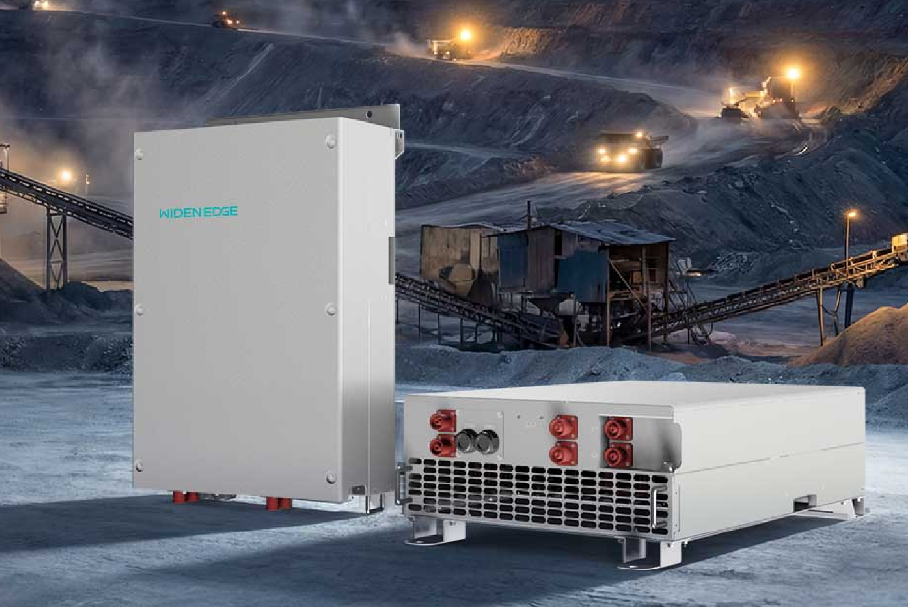
Problem-driven lead-in: Why a purpose-built 125 kW inverter is required
Grid frequency excursions, sustained voltage sag, and multi-hour outages require a deterministic response from storage inverters; a 125 kW commercial unit must be specified to meet those operational requirements. Engineers and microgrid companies routinely confront trade-offs in power electronics, thermal management, and control logic when sizing and deploying these systems, and the same set of decisions determines whether a site succeeds or fails operationally. Design teams that evaluate 125 kW inverters for distributed microgrid applications must reference field experience from large deployments (for example, Puerto Rico post-Hurricane Maria microgrid deployments) to avoid under-specified protection or inadequate commissioning procedures.
Core hardware components and their clinical roles
– Power conversion stage: bi-directional inverter using high-power semiconductor modules (IGBT or SiC) rated for continuous 125 kW and appropriate short-term overload. Specify switching frequency and thermal derating curves.
– DC bus and energy interface: DC link capacitors, pre-charge circuitry, and isolated DC/DC stages when coupling to different battery chemistries. Define maximum DC voltage, ripple limits, and time-to-trip thresholds.
– Battery management interface: analog and digital channels for State-of-Charge (SoC), State-of-Health (SoH), temperature sensors, and cell-string fault reporting. Control loops must accept precise SoC setpoints and limits.
– Grid interface and filters: LCL filters, transformer or galvanic isolation, and harmonic mitigation networks sized to meet total harmonic distortion (THD) targets and local grid-code limits.
– Protection hardware: AC and DC breakers, contactors, ground-fault detectors, and fast-acting disconnects with verified interrupting ratings.
– Environmental and mechanical systems: rated enclosure (NEMA/IK), forced-air or liquid cooling with redundancy, fire suppression provisioned to battery type, and access for safe maintenance.
– Telemetry and human interface: deterministic PLC-level controls, secure remote telemetry, and local HMI with fault logs and waveform capture capability.
Control architecture: algorithms and safety layers
– Hierarchical control: primary real-time inner loop for current control, secondary voltage/frequency regulation, tertiary energy management for scheduling and economic dispatch.
– Grid-forming vs grid-following: specify capability to operate as a grid-forming source for islanding with droop control, voltage reference stability, and synthetic inertia parameters when required.
– SoC management and cycling policy: active SoC constraints, depth-of-discharge guardrails, and charge/discharge ramp-rate limits to preserve battery life.
– Protection algorithms: anti-islanding detection with deterministic trip thresholds, unambiguous short-circuit response, and fault-tolerant synchronization routines.
– Communications and integrity: secure telemetry (TLS/VPN), deterministic device-to-device messaging for peer microgrid controllers, and firmware signature verification to prevent unauthorized updates.
Operational modes and practical use cases
– Emergency backup (fast-transfer): inverter configured for momentary islanding and seamless transfer with prioritized loads; must pass high-rate transient testing.
– Peak-shaving and demand-charge reduction: scheduled discharge windows with precise SoC forecasts and thermal derating compensation.
– Time-shifting for energy arbitrage: integration with price signals requires robust clock synchronization and safe override behavior during faults.
– PV smoothing and ramp mitigation: active power smoothing algorithms to limit injection gradients to prescribed kW/min rates.
– Grid services: frequency containment and synthetic inertia provision while maintaining battery SoC floor to avoid service interruption. These modes are typical across many microgrid applications and require clear mode-priority logic.
Common failure modes and prescriptive mitigations
– Thermal runaway risk from inadequate cooling: mitigate with redundant cooling loops, temperature trip points, and derating tables.
– DC link capacitor degradation causing increased ripple: specify endurance ratings and schedule capacitor ESR monitoring.
– Control instability during mode transitions: require closed-loop stability analysis, gain scheduling, and real-time diagnostic telemetry for phase-margin assessment.
– Communication loss between inverter and battery BMS: design safe default behavior (controlled shutdown or fixed-power fallback) and test failure modes during commissioning.
– Harmonic distortion exceeding limits: model harmonic spectra and verify LCL filter performance under worst-case switching and loading.
Testing, commissioning, and compliance checklist
– Factory Acceptance Test (FAT): waveform capture for steady-state and transient responses, functional verification of protection trips, and firmware version control.
– Site Acceptance Test (SAT): energization sequences, anti-islanding verification, synchronization with local grid or genset, and intentional-fault exercises under controlled conditions.
– Regulatory compliance: verify conformity with relevant standards (grid interconnection and safety standards common to commercial storage systems) and ensure documentation for local permitting authorities.
– Documentation and training: provide maintenance schedules, failure-mode charts, and operator training with hands-on scenarios to reproduce likely fault sequences.
Alternatives and selection criteria
– Centralized vs modular architecture: modular inverters simplify redundancy and serviceability; centralized units can be more cost-effective for single-point deployments—evaluate mean-time-to-repair and spare-part logistics.
– AC-coupled vs DC-coupled storage: DC-coupled configurations reduce conversion stages for co-located PV, but require compatible BMS and higher DC-voltage controls.
– Semiconductor choice (Si vs SiC): SiC reduces switching losses and cooling load at higher cost; select based on expected cycling profile and thermal envelope.
– Vendor integration model: single-vendor integrated solution reduces interface risk; best-of-breed requires rigorous interface control documents and factory-proven integration records.
Concluding synthesis
The operational problems that drive specification—frequency instability, sustained outages, and tight protection requirements—translate directly into measurable criteria for a 125 kW commercial inverter: defined overload capability, deterministic control hierarchies, and validated protection logic. Project teams that treat these criteria as testable requirements reduce commissioning time and operational risk; systems engineering continuity and field-proven commissioning routines deliver that outcome, and WidenEdge documents the engineering practices and on-site procedures that close those technical gaps.